Last Updated on June 21, 2026
Transforming a brilliant concept into a tangible product requires speed, precision, and the right tools. The journey from a digital file to a physical object is faster than ever, thanks to a diverse array of rapid prototyping methods. Each technique offers a unique set of advantages, whether you need to test a simple ergonomic form, validate complex mechanical functions, or create a visually perfect pre-production model. Understanding these options is critical for making smart, efficient development decisions.
This guide breaks down the essential methods engineers, designers, and innovators rely on to accelerate development, reduce costs, and bring better products to market. We will explore the core processes behind each technique, from additive approaches like 3D printing to subtractive ones like CNC machining. To better understand the fundamental differences between these manufacturing philosophies and how they impact prototyping choices, exploring a Subtractive vs. Additive Manufacturing: A Technical Comparison can be highly informative.
Instead of just a high-level overview, this article provides actionable details for each of the following rapid prototyping methods:
- 3D Printing (Additive Manufacturing)
- CNC Machining
- Laser Cutting
- Injection Molding (Prototype Tooling)
- Vacuum Casting (Polyurethane Casting)
- Sheet Metal Fabrication
- Electronic Prototyping (PCB and Breadboard)
- Digital Prototyping and Simulation
For each method, we will cover its core definition, key pros and cons, ideal use-case scenarios, and practical tool recommendations. This structured approach will help your team select the perfect method to validate your design, impress stakeholders, and move from idea to reality with confidence and speed.
1. 3D Printing (Additive Manufacturing)
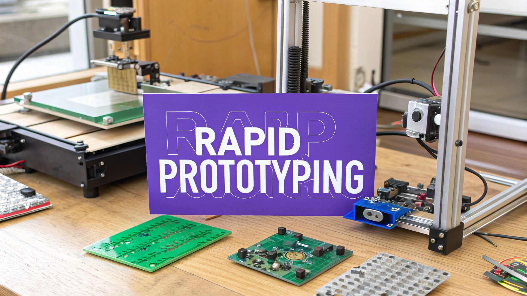
3D printing, also known as additive manufacturing, is one of the most transformative rapid prototyping methods available today. The process works by building a physical object from a digital CAD (Computer-Aided Design) file, depositing material layer by layer until the final form is complete. This bottom-up approach allows for the creation of intricate and complex geometries that would be impossible or prohibitively expensive to produce with traditional subtractive methods like CNC machining.
From automotive to aerospace, companies leverage 3D printing to accelerate innovation. For example, Airbus prototypes and produces aircraft interior components, reducing weight and assembly time. Similarly, Nike uses 3D printing for its Flyprint running shoe uppers, enabling rapid design iterations and customized fits for athletes. This direct path from digital design to a tangible object makes it an essential tool for validating form, fit, and function quickly.
When to Use 3D Printing
This method is ideal when you need to create a physical model with high geometric complexity in a short amount of time. It's perfect for early-stage conceptual models, functional prototypes for testing, and even custom jigs and fixtures for a manufacturing line. If your team needs to quickly test the ergonomics of a new product or verify the assembly of interlocking parts, 3D printing provides an unparalleled speed advantage.
The following infographic highlights the core advantages that make 3D printing a go-to choice for rapid prototyping.
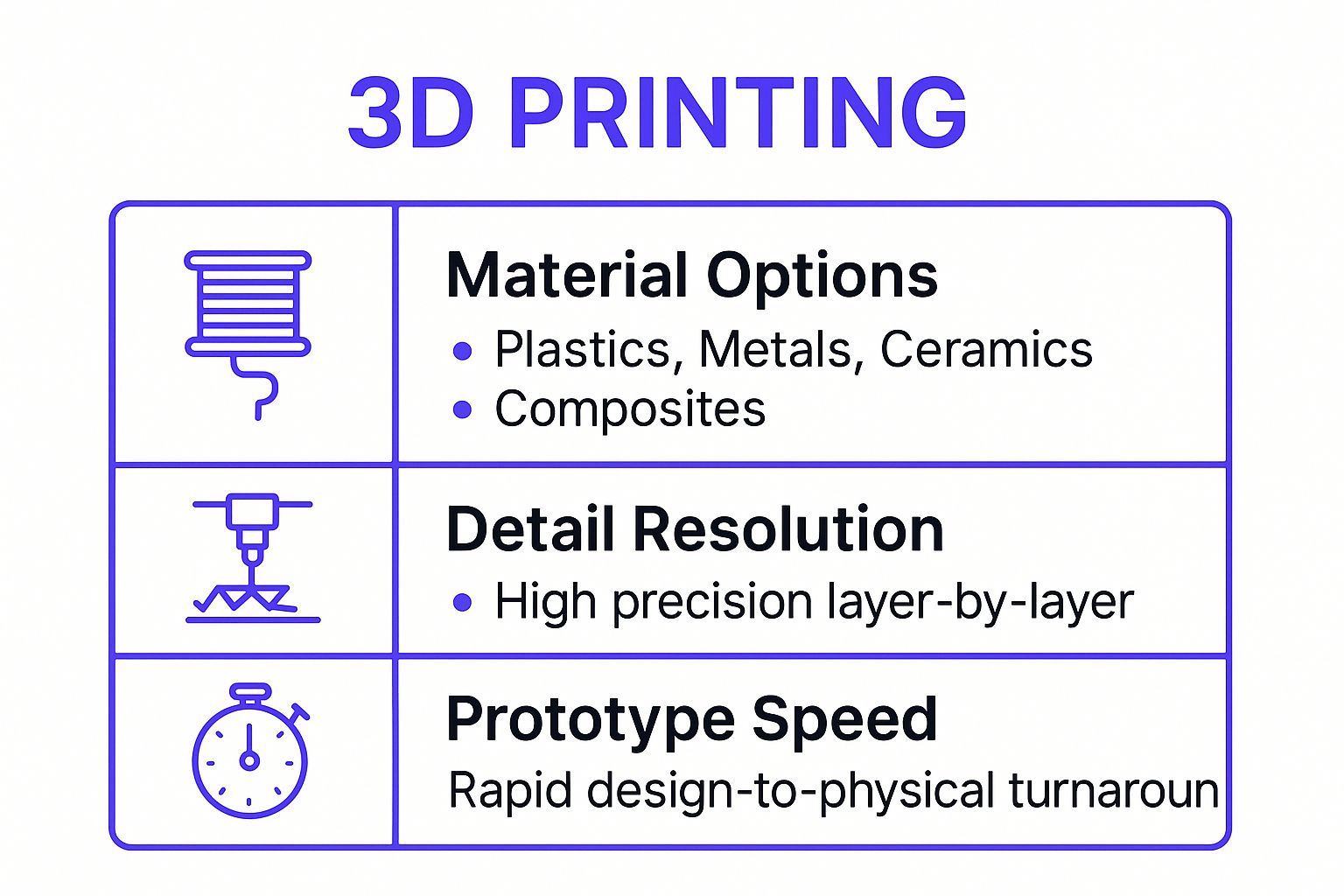
These key takeaways illustrate how the combination of material diversity, precision, and speed solidifies 3D printing's role as a cornerstone of modern product development.
Practical Tips for Implementation
To get the most out of 3D printing, keep these practical considerations in mind:
- Select the Right Technology: Choose the best printing method for your needs. Fused Deposition Modeling (FDM) is cost-effective for simple models, Stereolithography (SLA) offers high-detail and smooth surfaces, and Selective Laser Sintering (SLS) is great for strong, functional parts.
- Design for Additive: Optimize your CAD model for printing. Avoid steep overhangs that require extensive support structures, which add to print time and post-processing work.
- Optimize Print Orientation: The way you orient your model on the print bed directly impacts its strength and surface finish. Orient parts to minimize supports and align layers for maximum durability.
- Hollow Out Models: When possible, design parts to be hollow with an internal support structure (infill). This significantly reduces material consumption, cost, and print time without compromising integrity for most prototyping needs.
2. CNC Machining
Computer Numerical Control (CNC) machining stands as a powerhouse among rapid prototyping methods, operating on a subtractive principle. Unlike 3D printing, this process starts with a solid block of material (a workpiece) and uses computer-controlled cutting tools to precisely remove material, carving out the final part from a digital CAD file. This method is renowned for creating prototypes with exceptional strength, tight tolerances, and superior surface finishes.
Many leading technology companies rely on CNC machining for high-fidelity prototypes that mimic final production parts. For instance, Apple extensively uses CNC machining to create the precise unibody aluminum enclosures for its MacBooks and iPhones. In the automotive sector, Tesla employs CNC to prototype and produce critical components for its vehicles, ensuring structural integrity and precise fit. This ability to work with production-grade materials makes it invaluable for functional and mechanical testing.
When to Use CNC Machining
CNC machining is the ideal choice when your prototype requires high dimensional accuracy, superior strength, and an excellent surface finish using production-intent materials like metal or high-performance plastics. It's perfectly suited for functional prototypes that will undergo rigorous mechanical stress testing, fit checks with other components, or when you need a prototype that closely resembles a final manufactured part in both look and feel.
The precision and material compatibility offered by CNC machining are crucial for verifying a design's mechanical performance before committing to expensive mass-production tooling. It bridges the gap between a digital concept and a robust, testable physical object.
Practical Tips for Implementation
To optimize your CNC machining process for rapid prototyping, consider the following practical tips:
- Design for Manufacturability: Keep machining constraints in mind. Avoid features like deep, narrow pockets or extremely thin walls that are difficult for cutting tools to access and can lead to tool breakage or vibration.
- Specify Appropriate Tolerances: Only apply tight tolerances where absolutely necessary. Over-tolerancing parts significantly increases machining time and cost, as it requires more precise setups and slower cutting speeds.
- Leverage Standard Tool Sizes: Design internal corners and features to accommodate standard end mill sizes. Using custom tools adds unnecessary complexity and expense to the prototyping stage.
- Consider Material Properties: Think about the material's grain direction, especially with metals, to maximize the part's strength. Also, choose a material that balances your performance needs with machinability and cost.
3. Laser Cutting
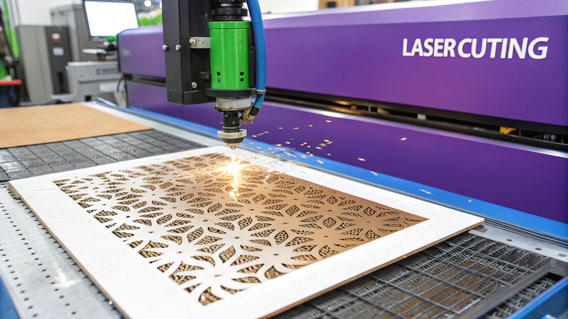
Laser cutting is a subtractive manufacturing process that uses a high-powered, focused laser beam to cut, etch, or engrave materials with exceptional precision. This rapid prototyping method works by directing the laser output through optics to a specific point, melting, burning, or vaporizing the material to create a clean, highly accurate cut. The process is computer-controlled, translating a digital design file directly into a physical part made from sheet materials.
This technology is widely used across various industries for its speed and versatility. For instance, architecture firms create incredibly detailed scale models by assembling laser-cut components from acrylic and wood. In electronics, companies like SparkFun and Adafruit prototype custom enclosures and mounting panels for their hardware, ensuring a perfect fit for circuit boards and connectors. The automotive sector also relies on laser cutting to quickly produce prototype gaskets, brackets, and interior trim pieces for fitment tests.
When to Use Laser Cutting
This method is best suited for creating high-precision 2D parts from flat sheet materials like acrylic, wood, metal, cardboard, and fabric. It is the perfect choice when you need to quickly produce structural components, custom enclosures, stencils, or intricate decorative elements. If your prototype consists of flat panels that will be assembled into a 3D object, or if you need to test a mechanism made from flat interlocking parts, laser cutting offers a fast and cost-effective solution with excellent edge quality.
The precision and speed of laser cutters make them a foundational tool for product developers who need to move quickly from a digital drawing to a functional, tangible part.
Practical Tips for Implementation
To maximize the effectiveness of laser cutting in your prototyping workflow, consider these practical tips:
- Design with Kerf in Mind: The laser burns away a small amount of material, known as the "kerf." For parts that need to fit together precisely, you must compensate for this kerf in your design files to ensure tight-fitting assemblies.
- Use Vector Graphics: Laser cutters operate using vector files (like DXF, SVG, or AI). Ensure your designs are created in a vector format for clean, continuous cutting paths, as opposed to raster formats like JPG or PNG.
- Plan for Tabs or Micro-Joints: To prevent small, delicate parts from falling out of the main sheet during the cutting process, incorporate tiny tabs or micro-joints into your design to hold them in place. These can be easily snapped or sanded off later.
- Optimize Your Layout: Arrange your parts as closely as possible on the material sheet (a process called nesting) to minimize material waste and reduce cutting time, which in turn lowers the cost of your prototype.
4. Injection Molding (Prototype Tooling)
Prototype injection molding is one of the most effective rapid prototyping methods for creating high-fidelity plastic parts that closely mimic final production quality. Unlike 3D printing, this process involves injecting molten plastic into a mold, or tool, to form the part. For prototyping, these molds are typically made from softer, faster-to-machine materials like aluminum instead of the hardened steel used for mass production, significantly reducing lead time and cost.
This approach is invaluable for late-stage prototyping and low-volume production. For instance, consumer electronics companies use prototype molding to create dimensionally accurate housings for devices like smart speakers, ensuring a perfect fit for internal components before committing to expensive production tooling. Similarly, automotive suppliers test interior trim components for snap-fit functionality and surface finish, validating designs with production-grade materials. This method provides an authentic preview of the final product's look, feel, and performance.
When to Use Injection Molding
This method is best when you need parts with superior surface finish, tight tolerances, and mechanical properties representative of a final product. It is the ideal bridge between 3D-printed models and full-scale manufacturing. If you need to produce a few hundred to a few thousand units for pilot runs, functional testing, or market validation, prototype injection molding offers an unbeatable combination of quality and speed. This stage is crucial after you've used other methods to prioritize which product features to validate.
The ability to use the actual production plastic (like ABS, Polycarbonate, or Nylon) allows for realistic functional and environmental testing that other prototyping methods cannot replicate.
Practical Tips for Implementation
To successfully implement prototype injection molding, consider the following best practices:
- Opt for Aluminum Tooling: Use aluminum molds for prototype runs. They are significantly cheaper and faster to fabricate than steel tools and are easily modified if design tweaks are needed.
- Design for Manufacturability (DFM): Ensure your CAD model adheres to injection molding principles. Incorporate proper draft angles to allow parts to eject cleanly, maintain uniform wall thickness to prevent sink marks, and add radii to corners to improve material flow.
- Plan Gate and Ejector Pin Locations: Work with your molding partner to strategically place gates (where plastic enters the mold) and ejector pins. Poor placement can leave undesirable cosmetic blemishes on visible surfaces.
- Clarify Quantity Needs: Be clear about how many parts you need. The expected quantity will determine the mold's design and material, impacting its lifespan and overall cost. A tool designed for 500 shots will be different from one designed for 5,000.
5. Vacuum Casting (Polyurethane Casting)
Vacuum casting, often called polyurethane casting, is a highly effective rapid prototyping method for producing small batches of high-quality prototypes. The process begins with a master model, typically created via 3D printing (SLA) or CNC machining, which is then suspended in a casting box and encased in liquid silicone. Once the silicone mold cures, it is cut open, and the master model is removed, leaving a detailed cavity. The mold is then placed in a vacuum chamber, where liquid polyurethane resin is poured into the cavity, ensuring no air bubbles are trapped.
This technique is widely used for creating prototypes that closely mimic the look, feel, and performance of final injection-molded parts. For instance, automotive companies use vacuum casting to create dashboard and trim prototypes with production-level finishes. Likewise, consumer product companies rely on it to produce realistic housings and covers for user testing and marketing photos, validating both aesthetics and ergonomics before committing to expensive tooling. This ability to generate multiple, consistent copies makes it a vital step in the product development process.
When to Use Vacuum Casting
Vacuum casting is the ideal choice when you need a small series of parts (typically 10-50 units) with a superb surface finish and material properties comparable to production plastics. It bridges the gap between a single 3D-printed model and full-scale manufacturing. It is perfect for market validation, functional testing with multiple units, or creating a set of pre-production models for a trade show. If you need parts in various colors, textures, or different levels of hardness (from rigid to rubber-like), this method provides excellent flexibility.
Practical Tips for Implementation
To achieve the best results with vacuum casting, consider these practical guidelines:
- Design a High-Quality Master Pattern: The final part is only as good as the master. Use a high-resolution 3D printing method like SLA or CNC machining for a smooth, detailed master pattern and apply a finish to remove any layer lines.
- Plan for Mold Parting Lines: Work with your manufacturing partner to determine the best location for the parting line on the silicone mold. This will affect where faint witness marks may appear on the final parts.
- Incorporate Draft Angles: Design your master pattern with slight draft angles (typically 1-2 degrees) on vertical faces. This makes it much easier to demold the cast parts without damaging the silicone mold, extending its life.
- Select the Right Resin: Polyurethane resins are available in a wide range of properties. Choose the appropriate shore hardness and material characteristics (e.g., UV resistance, flexibility, rigidity) to match the requirements of your end-product.
6. Sheet Metal Fabrication
Sheet metal fabrication is one of the most fundamental rapid prototyping methods for creating durable, functional metal parts. The process involves cutting, bending, forming, and assembling thin sheets of metal (typically steel, aluminum, or stainless steel) to create a final product from a CAD design. Common techniques include laser cutting, waterjet cutting, punching, and bending with a press brake, allowing for the rapid creation of strong, lightweight components.
This method is critical for industries that rely on metal enclosures, brackets, and structural parts. For instance, manufacturers of electronic devices use sheet metal fabrication to prototype server chassis and equipment enclosures, ensuring proper fit for internal components and effective thermal management. In the automotive sector, teams prototype new brackets and body panels to test their strength and assembly feasibility before committing to expensive production stamping dies. This direct path from a digital file to a sturdy metal part is essential for validating designs that require high strength and durability.
When to Use Sheet metal Fabrication
This method is ideal when you need to create robust metal prototypes that accurately represent final production parts. It is perfect for functional testing of enclosures, chassis, brackets, and panels where strength, heat dissipation, and structural integrity are critical. If your prototype needs to withstand physical stress or serve as a housing for electronic components, sheet metal fabrication provides a fast and cost-effective solution that closely mimics mass-production quality.
Practical Tips for Implementation
To get the most out of sheet metal fabrication, keep these practical considerations in mind:
- Design for Standard Tooling: Use standard bend radii and hole sizes whenever possible. Designing around common tooling available at fabrication shops like those using Amada or Trumpf machinery avoids the cost and lead time associated with custom tools.
- Account for Material Properties: Pay close attention to the material's grain direction when designing bends. Bending parallel to the grain can cause cracking, so orient bends perpendicular to the grain for maximum strength.
- Incorporate Bend Relief: Add small cuts or reliefs at the edge of a bend line. This prevents the material from tearing or deforming during the bending process, ensuring clean corners and accurate angles.
- Define Clear Tolerances: Sheet metal has inherent variability. Specify critical tolerances on your drawings but keep non-critical dimensions more flexible to reduce manufacturing complexity and cost.
7. Electronic Prototyping (PCB and Breadboard)
Electronic prototyping is one of the most critical rapid prototyping methods for products with electrical components. It involves building and testing circuits, from simple solderless breadboards for initial concept validation to custom Printed Circuit Boards (PCBs) for near-production-ready models. This process is essential for verifying functionality, testing component interactions, and developing embedded systems before committing to expensive mass production.
Companies rely on electronic prototyping to bring smart devices to life. For instance, developers of IoT devices use breadboards and modular platforms like Arduino to quickly assemble and test wireless connectivity and sensor functionality. In the automotive industry, engineers create custom PCBs to prototype and test new Electronic Control Units (ECUs) in real-world conditions. This iterative process of building, testing, and refining circuits de-risks product development and accelerates the path from an idea to a functional electronic device.
When to Use Electronic Prototyping
This method is indispensable whenever a product involves electronics. Use it for early-stage validation of circuit diagrams, functional testing of software on target hardware, or creating robust prototypes for user testing and certification. If you need to test a sensor’s accuracy, validate a power management circuit, or ensure firmware runs correctly on your chosen microcontroller, electronic prototyping provides the necessary framework for tangible, data-driven validation.
For teams, especially remote ones, this hands-on approach is invaluable for troubleshooting and collaborative problem-solving. It transforms abstract schematics into physical systems that can be debugged and improved, fostering innovation in remote teams by enabling parallel hardware and software development.
Practical Tips for Implementation
To get the most out of electronic prototyping, keep these practical considerations in mind:
- Start with a Breadboard: Always begin with a solderless breadboard for initial circuit validation. It allows you to quickly assemble, test, and modify circuits without permanent connections, saving significant time and resources.
- Leverage Modular Development Boards: Use platforms like Arduino, Raspberry Pi, or ESP32 for rapid development. These boards come with integrated microcontrollers and peripherals, providing a solid foundation to build upon.
- Plan Your PCB Layout Carefully: When moving to a PCB, consider manufacturability and assembly from the start. Proper component placement, trace routing, and clearance are crucial for a reliable and functional board.
- Include Debugging Interfaces: Design your PCBs with test points, JTAG/SWD headers, and status LEDs. These features are invaluable for troubleshooting and programming the device during and after assembly.
- Use Simulation Software First: Before ordering physical boards, use software like KiCad, Altium, or Autodesk EAGLE to simulate circuit behavior. This helps catch design flaws early and reduces the number of costly board revisions.
8. Digital Prototyping and Simulation
Digital prototyping is one of the most cost-effective and powerful rapid prototyping methods, enabling teams to test and validate designs entirely within a virtual environment. The process uses advanced software to create a digital twin of a product, which can then be subjected to a wide range of simulations, including Finite Element Analysis (FEA) for structural integrity and Computational Fluid Dynamics (CFD) for aerodynamics. This computer-based approach allows for countless iterations without ever building a physical object.
This method is crucial in high-stakes industries where physical testing is expensive or impossible. For instance, Formula 1 teams use CFD simulations to refine the aerodynamics of their cars, gaining performance advantages measured in milliseconds. Similarly, medical device companies use digital prototypes to simulate how an implant will perform under various biomechanical loads inside the human body, ensuring safety and efficacy long before clinical trials begin.
When to Use Digital Prototyping and Simulation
This method is ideal for the very early stages of development when you need to analyze a product's performance under specific conditions without incurring the costs of physical manufacturing. It's perfect for optimizing complex systems, predicting failure points, and testing variables that would be difficult to control in the real world. If your team needs to understand how a product will react to heat, stress, or fluid flow, simulation provides precise, data-driven insights. This is an essential step for teams using remote product development tools to collaborate on complex engineering challenges.
By creating digital mockups, teams can also refine user interfaces and experiences. For software or app development, understanding what a component library is can drastically accelerate the creation of these digital prototypes and ensure design consistency across the board. These digital-first approaches save immense time and resources.
Practical Tips for Implementation
To maximize the effectiveness of digital prototyping and simulation, consider these practical tips:
- Start Simple: Begin with simplified models to test fundamental assumptions. Gradually add complexity as the design matures to avoid over-complicating early-stage analysis.
- Validate with Real Data: Whenever possible, use data from a physical test to validate your simulation model's accuracy. This builds confidence in the virtual results.
- Mind the Mesh: In FEA or CFD, the quality and density of your simulation mesh directly impact accuracy and computation time. Use a finer mesh in critical areas and a coarser one elsewhere.
- Document Assumptions: Clearly document all assumptions, boundary conditions, and limitations of each simulation. This context is crucial for interpreting the results correctly.
Rapid Prototyping Methods Comparison
| Method | Implementation Complexity 🔄 | Resource Requirements 💡 | Expected Outcomes 📊 | Ideal Use Cases 💡 | Key Advantages ⭐ / ⚡ |
|---|---|---|---|---|---|
| 3D Printing (Additive Manufacturing) | Moderate 🔄🔄 | Moderate: Printers, materials (plastics, metals) | Rapid prototypes with complex geometries 📊⭐ | Rapid prototyping, complex shapes, low-volume parts | Fast turnaround ⚡, low material waste, mass customization ⭐ |
| CNC Machining | High 🔄🔄🔄 | High: Skilled operators, cutting tools, materials | Precise, production-grade parts with fine finish 📊⭐ | Functional testing, metal/plastic parts, tight tolerances | High precision and surface finish ⭐, repeatable results |
| Laser Cutting | Low to Moderate 🔄 | Moderate: Laser equipment, sheet materials | Fast, precise 2D cuts and engravings 📊 | Sheet-based parts, enclosures, intricate flat designs | Very fast ⚡, clean edges, no tooling cost |
| Injection Molding (Prototype Tooling) | High 🔄🔄🔄 | High: Tooling fabrication, production materials | Production-like plastic parts 📊⭐ | Functional testing, small batch production, validation | Production-grade parts ⭐, cost-effective for medium runs |
| Vacuum Casting (Polyurethane Casting) | Moderate 🔄🔄 | Moderate: Master pattern, silicone molds, vacuum setup | Small batch plastic prototypes with good finish 📊 | Small quantity prototypes with production-like properties | Good surface finish ⭐, lower cost than CNC, complex shapes |
| Sheet Metal Fabrication | Moderate to High 🔄🔄🔄 | High: Fabrication equipment, skilled labor | Durable metal prototypes, enclosures 📊⭐ | Metal enclosures, structural components, scalable prototypes | Uses real materials ⭐, excellent mechanical properties |
| Electronic Prototyping (PCB and Breadboard) | Low to Moderate 🔄 | Moderate: Components, breadboards, PCB fabrication | Functional electronics for testing and development 📊 | Circuit validation, embedded system prototyping | Quick iteration ⚡, easy modification, co-development of hardware/software |
| Digital Prototyping and Simulation | High 🔄🔄🔄 | High: Software licenses, computational resources | Virtual testing and optimization 📊 | Early design validation, complex performance simulation | Fast iterations ⚡, cost-effective, safe testing of extremes ⭐ |
Innovate Faster by Prototyping Smarter
We've journeyed through a comprehensive landscape of modern rapid prototyping methods, from the additive magic of 3D printing to the subtractive precision of CNC machining and the virtual fidelity of digital simulations. Each technique offers a unique set of capabilities, and understanding their individual strengths is the first step toward mastering product innovation. The core lesson is clear: there is no single "best" method. Instead, the most successful product teams build a flexible, multi-stage prototyping strategy.
The power of this approach lies in its adaptability. You can move from a low-cost, fast-turnaround FDM 3D print for initial form and fit checks, to a high-precision CNC-machined part for rigorous functional testing, and finally to a small batch of vacuum-cast units for user feedback sessions. This strategic progression ensures you're always using the most cost-effective and appropriate tool for the task at hand, minimizing waste and accelerating your development cycle.
Your Prototyping Flywheel: From Idea to Reality
Think of your product development process not as a linear path, but as a flywheel. Each successful prototype adds momentum, allowing you to learn, iterate, and build speed. The key is to match the prototyping method to your specific learning objective at each stage.
- For Early-Stage Validation (Is this idea viable?): Start with Digital Prototyping and 3D Printing. These methods are unparalleled for their speed and low cost, allowing you to quickly visualize concepts, test ergonomics, and get stakeholder buy-in without significant investment.
- For Functional Testing (Does this work as intended?): Transition to CNC Machining, Laser Cutting, and Sheet Metal Fabrication. When you need to test mechanical strength, thermal properties, or the integration of moving parts, these methods provide the material accuracy and durability required for real-world performance validation.
- For Pre-Production and Market Fit (Will customers love this?): Use Vacuum Casting and Prototype Injection Molding. These techniques are perfect for creating high-fidelity, aesthetically pleasing models in small batches. They bridge the gap to mass production, enabling you to conduct user testing, create marketing materials, and secure final approvals with parts that look and feel like the finished product.
Mastering this strategic selection of rapid prototyping methods is a competitive advantage. It empowers your team to fail faster, learn smarter, and ultimately, get to market with a more refined and validated product. The goal isn't just to build a prototype; it's to build the right prototype at the right time to answer your most critical questions.
The Foundation of Great Prototypes: Great Ideas
However, even the most advanced prototyping workflow is only as good as the ideas that fuel it. A flawless prototype of a flawed concept is still a flawed concept. This is where the innovation process truly begins, long before the first CAD file is created or the first 3D printer whirs to life. For remote and hybrid teams, fostering a creative environment for generating and refining these foundational ideas can be a significant challenge.
The quality of your initial brainstorming and ideation directly dictates the potential of your final product. A structured, engaging, and inclusive ideation process ensures that you're not just iterating on the first idea that comes to mind, but exploring the full spectrum of possibilities. By investing in the quality of your concepts from day one, you ensure that every subsequent dollar and hour spent on prototyping is a step toward a truly innovative solution. This upstream focus makes the entire downstream development process more efficient, purposeful, and likely to succeed.
Before you start your next 3D print or CNC job, ensure your core idea is as strong as it can be. Bulby provides AI-powered tools and structured brainstorming exercises designed to help your remote team unlock its creative potential and generate truly groundbreaking concepts. Start with a stronger foundation and make every prototype count by visiting Bulby today.